Coastal storms bring more than just rain and wind; they unleash the immense power of salt water hydrostatic pressure, a force that is the most significant challenge for any reliable flood barrier system. At Water Gate Systems, we understand this force intimately, and our designs, like the Aqua Cade Barrier, are engineered to not just withstand it, but to conquer it.
Understanding Hydrostatic Pressure Fundamentals
Unlike the relatively constant air pressure we experience daily, hydrostatic pressure behaves differently: it increases linearly with depth. This creates a triangular pressure distribution that places the maximum stress exactly where a barrier is most vulnerable—at its lowest points.
The core physics of this is captured by the fundamental equation:
P=ρgh
- P represents the hydrostatic pressure.
- ρ (rho) is the fluid density (for salt water, this is approximately 64 pounds per cubic foot (lb/ft³)).
- g is the gravitational acceleration (32.2 ft/s²).
- h indicates the depth below the water surface.
This seemingly simple relationship has profound implications for the structural integrity and design of flood barriers8.
Pressure Distribution on a 6-Panel Barrier System
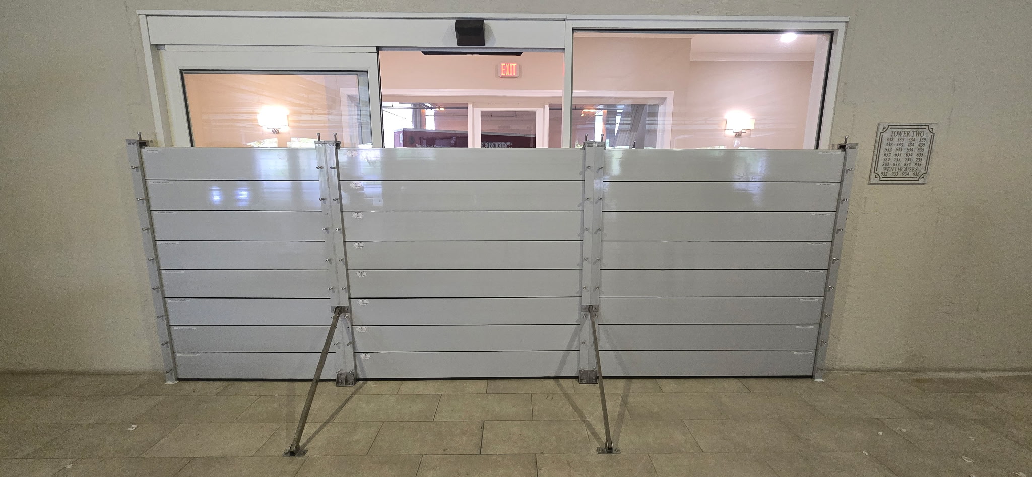
Let’s look at a common scenario: a flood barrier system measuring 17 feet wide by 47.22 inches high, consisting of six horizontally stacked panels. Each panel is 7.87 inches high and 1.4375 inches thick.
In a three-foot flood scenario (36 inches of water):
- The water will completely submerge the bottom four and a half panels.
- Pressure starts at zero at the water’s surface.
- It increases linearly to a maximum of 192 pounds per square foot (psf) at the three-foot depth mark, calculated as: 64 lb/ft3×3 ft=192 psf.
This gradient creates a triangular load distribution across the submerged barrier. The pressure on the panels, from bottom to top, is substantial and can be clearly visualized:
| Panel (from bottom) | Height (inches) | Pressure Range (psf) |
| 1 (Bottom) | 0 to 7.87 | 155.2 to 192 |
| 2 | 7.87 to 15.74 | 117.6 to 155.2 |
| 3 | 15.74 to 23.61 | 80 to 117.6 |
| 4 | 23.61 to 31.48 | 42.4 to 80 |
| 5 (Partially Submerged) | 31.48 to 36 | 0 to 42.4 |
| 6 (Above Water) | 36 to 47.22 | 0 |
Critical Pressure Zones and Structural Implications
The maximum hydrostatic pressure, 192 psf, is concentrated at ground level. This base concentration is why the bottom panel must be engineered to resist not only the direct hydrostatic pressure but also the cumulative overturning moment from the entire pressure distribution.
For the 17-foot wide barrier, the total hydrostatic force is substantial:
(0.5×192 psf×3 ft)×17 ft=4,896 pounds
This force creates an equal overturning moment of 4,896 foot-pounds about the base of the barrier. The resultant hydrostatic force acts at the center of pressure, which is located at two-thirds of the submerged depth from the water surface, or approximately 24 inches above ground level.
Center Post Loading and Support Requirements
The center support post plays a crucial role, bearing approximately
half of the total hydrostatic load, or roughly 2,448 pounds. The end connections must resist 1,224 pounds each. However, the greatest structural challenge is maximum bending stress, which occurs not at the point of maximum pressure, but at approximately 12 inches above ground level. This is the sweet spot where the high pressure magnitude and the moment arm length create the largest moment.
Furthermore, static loads are compounded by dynamic components:
- High winds can add 20-30 psf in lateral pressure.
- Debris impact can generate instantaneous forces exceeding 1,000 pounds at localized points.
Optimal Tension Brace Placement Strategy
Based on rigorous structural analysis, the most effective way to counteract the forces on the center support post is through the optimal placement of a tension brace.
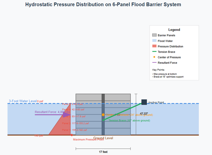
The ideal height for the tension brace connection is 18 inches above ground level.
Why 18 Inches is Critical:
- Counteracts Overturning Moment: This 18-inch height places the brace connection slightly below the center of pressure (24 inches). This allows the brace to effectively counteract the overturning moment while maintaining high structural efficiency.
- Prevents Excessive Deflection: Positioning the brace too low reduces its mechanical advantage, while positioning it too high allows excessive deflection in the lower, high-pressure zone.
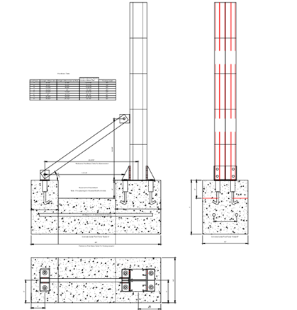
The tension brace should be extended at about a 45-degree angle to solid anchor points. For this application, the required brace tension is approximately 3,500 pounds, requiring substantial anchoring.
Competitor Misstep Alert: We routinely see our competitors place the brace too high to properly support cyclical loads seen in hurricane conditions.
The proper footings, as shown in our cut sheet, are equally critical to your Aqua Cade Barrier performing properly exactly when you need it.
Dynamic Load Considerations and Design Recommendations
Storm surge introduces dynamic amplification factors that can increase static loads by 20–40%.
Wave action creates cyclic loading that can lead to fatigue issues in connections. The combination of sustained hydrostatic pressure with dynamic impacts requires robust connection details and adequate safety factors. Furthermore, debris loading from logs, vehicles, or other large objects carried by floodwater can impact individual panels with tremendous force, potentially compromising the barrier integrity if connections cannot redistribute these concentrated loads.
Design and Safety Factors:
| Design Element | Structural Requirement |
| Panel Support | Bottom two panels require most robust connections (experience 70% of total load) |
| Static Safety Factor | Minimum of 2.0 for static loads |
| Dynamic Safety Factor | Minimum of 3.0 for combined static and dynamic conditions |
| Material Specification | Stainless steel hardware rated for marine environments for corrosion resistance |
| Deflection Limit | Should not exceed L/240 under design loads for the 17-foot span |
Regular inspection protocols are critical, as salt water accelerates corrosion of metallic components. The 17-foot span necessitates careful consideration of panel deflection limits, as excessive deflection can compromise seal integrity.
Conclusion
Salt water hydrostatic pressure creates a complex loading environment for flood barrier systems, with maximum pressures occurring at ground level and critical stress concentrations at the center support post. For a typical garage opening of 17 feet and 6 panels. The recommended tension brace placement at 18 inches above ground level optimizes structural performance while providing practical installation advantages. Success requires careful attention to connection details, material selection, and regular maintenance protocols to ensure reliable performance during critical flood events.